Enhancing Your Traffic Management: Installing an 11-Pin Loop Detector Harness: Traffic control systems are critical for managing the flow and safety of vehicles at key points such as intersections, exits, and entryways. A core component of these systems is the loop detector harness, which connects inductive loop sensors embedded in the roadway to the traffic control system. This blog post expands on our previous discussion about loop detector harnesses by diving into the specifics of installing an 11pin harness, which is commonly used in traffic management systems.
Detailed Connection Guide for an 11Pin Loop Detector Harness
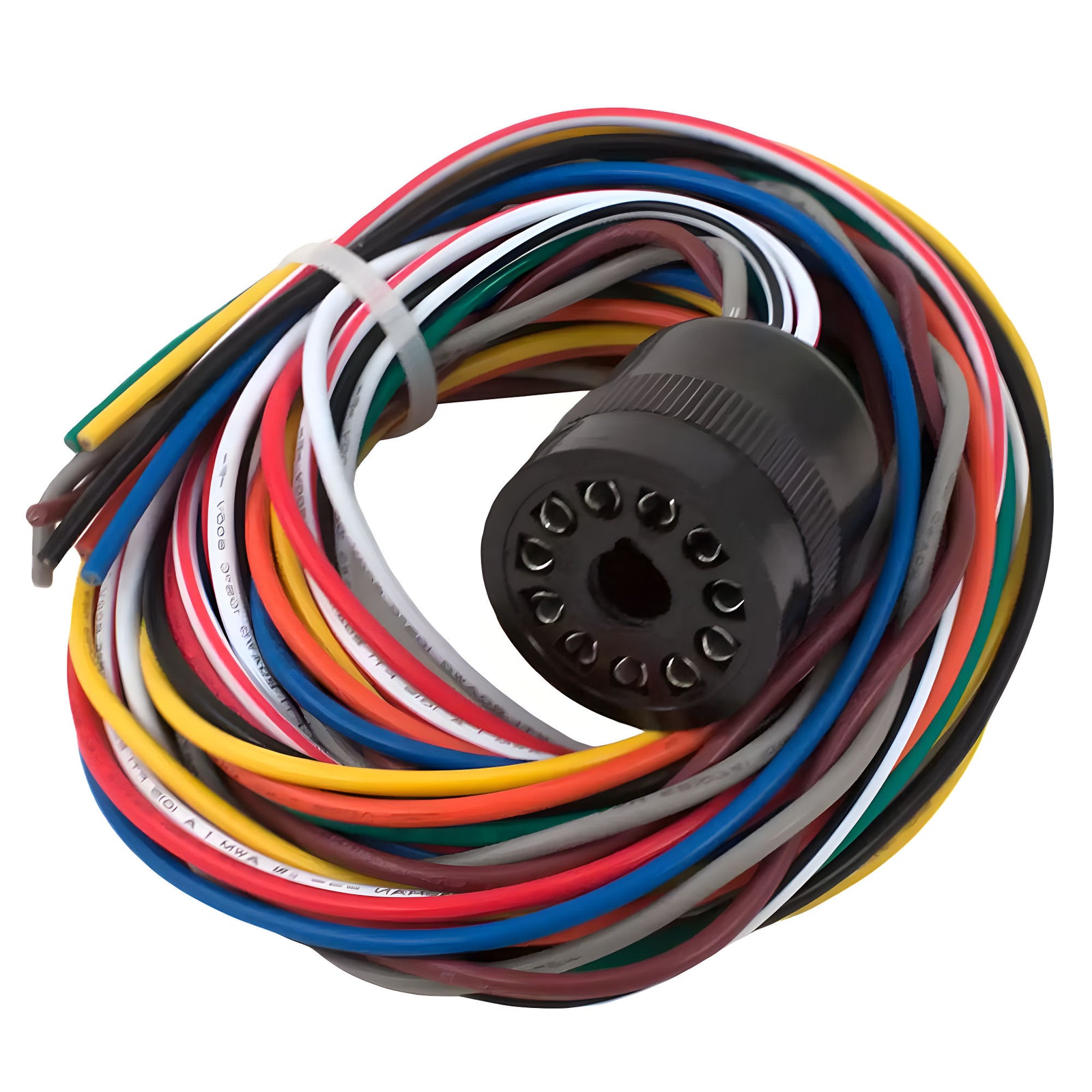
The 11-pin loop detector harness is versatile and can be adapted to different functions based on the traffic management needs, such as exit gates, safety measures, or general vehicle detection. Here’s how to correctly connect this type of harness:
Power Connections: Black/White Wires: These are used for power connections. The black wire typically connects to the positive (+) terminal, and the white wire connects to the negative (-) terminal. The voltage requirements (12V or 240V) depend on the loop detector model.
Connecting to the Inductive Loop: Gray/Brown Wires: These wires are responsible for connecting to the underground inductive loop. The gray wire is usually connected to one end of the loop, and the brown wire to the other, forming a continuous loop circuit that can detect vehicle presence through inductance changes.
Integration with the Control System: Yellow/Blue Wires: These wires are crucial for integrating the loop detector with the gate opener’s main control board. The yellow wire is normally open (NO), and the blue wire serves as the common connection.
Here are some typical uses for automatic gate loops:
- Exit Loop: If the loop is intended for controlling an exit gate, these wires should be connected to the exit terminals on the main control board.
- Safety or Reverse Loop: If the loop functions as a safety measure to prevent gate closure on an obstructing vehicle or to trigger a gate to reopen, connect these wires to the safety or reverse loop terminals.
- Phantom or Center Loop: For swing gates and specialized applications, such as counting vehicles or managing speeds, connect to the designated terminals for phantom or center loops on the main control board.
Important Installation Tips:
- Ensure Proper Insulation: Connections should be well insulated to prevent electrical shorts and interference with signal transmission.
- Follow Manufacturer's Guidelines: Always refer to the manufacturer’s instructions for specifics regarding terminal connections, wire color coding, and voltage settings.
- Test the System: After installation, thoroughly test the system with actual vehicles to ensure that the loop correctly detects vehicle presence and communicates effectively with the control system.
Conclusion
Understanding the specifics of the 11-pin loop detector harness and its connection process is essential for enhancing traffic management systems. By following these detailed instructions, technicians can ensure that they are setting up their systems for optimal performance and safety. Whether managing a busy intersection, a controlled parking lot entry, or an automated gate system, the correct installation of a loop detector harness is key to achieving efficient and reliable traffic management.
This enhanced guide provides you with a deeper understanding of how to manage and install these systems effectively. For those in the field, these insights can help streamline operations and ensure that traffic control technologies are utilized to their fullest potential. For more information about loops see our inductive loop section.